Eagle Hints

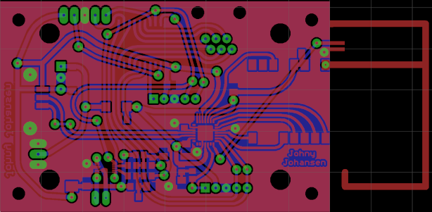
When using Eagle for the home production of prints, getting a proper artwork is not easy.
Encountering the following problems (Eagle version 6.5.0):
- Way too coarse resolution when printing the board.
- If you generate PNG files instead, there are several problems such as missing holes, sometimes pixel errors.
- It is difficult to drill the print, the holes are far too large to help with centering.
- Holes are etched on both the upper and lower sides, which increases the requirements for alignment.
To solve this, I have made a ULP and an SCR program which solves these problems. The programs are listed below.
I have a laser printer that can print at 1200 dpi, which is an OK resolution for my prints.
To generate the PNG files for the printer, I run the generate-png.scr script. This calls, among other things, a-drill-aid.ulp, which is a further development of Eagle's drill-aid.ulp.
The result is a top layer with 0.4 mm holes, works well as a centering agent for a 0.8 mm drill. The bottom layer has pads without holes. This means that there is more copper if the top and bottom layers are not well aligned.
You must (unfortunately) edit the files yourself to mirror the top layer and stop mask, and all the files must be color inverted.
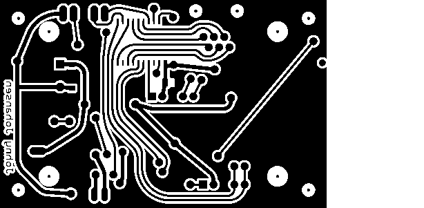
Results
The resulting top and bottom layers are shown here at 1/8 resolution (the holes in the left image are smaller in reality, smaller than the small black dots in the right image):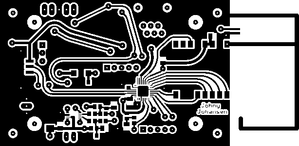
The SCR program
display none 116 117 118;group all;
delete (> 0 0);
group;
# Make layers drillAidInner, drillAidOuter and holeFill
run a-drill-aid.ulp
grid mm;
display none Vias Bottom Pads holeFill;
RATSNEST;
EXPORT IMAGE copperBottom.png MONOCHROME 1200;
# Make small holes in the top layer vias for better manual drilling
display none Vias Top Pads drillAidOuter drillAidInner;
RATSNEST;
EXPORT IMAGE copperTop.png MONOCHROME 1200;
SET FILL_LAYER tStop solid;
display none tStop;
EXPORT IMAGE stopTop.png MONOCHROME 1200;
SET FILL_LAYER bStop solid;
display none bStop;
EXPORT IMAGE stopBottom.png MONOCHROME 1200;
The ULP program
real fillDiameter = 0.8; // diameter of the via holesreal drillAidDiameter = 0.4; // diameter of the drill aid hole
string cmd = "GRID mm;\n";
cmd += "Layer 116 holeFill;\nSET FILL_LAYER holeFill solid;\nSET COLOR_LAYER holeFill 2;\n";
cmd += "Layer 117 drillAidInner;\nSET FILL_LAYER drillAidInner solid;\nSET COLOR_LAYER drillAidInner 0;\n";
cmd += "Layer 118 drillAidOuter;\nSET FILL_LAYER drillAidOuter solid;\nSET COLOR_LAYER drillAidOuter 2;\n";
void center(int x, int y) {
string h;
cmd += "change layer holeFill;\n";
sprintf(h, "circle %.3f (%.3f %.3f) (%.3f %.3f) ;\n",
0.0,
u2mm(x), u2mm(y), u2mm(x) + fillDiameter / 2, u2mm(y) );
cmd += h;
cmd += "change layer drillAidInner;\n";
sprintf(h, "circle %.3f (%.3f %.3f) (%.3f %.3f) ;\n",
0.0,
u2mm(x), u2mm(y), u2mm(x) + fillDiameter / 2, u2mm(y) );
cmd += h;
cmd += "change layer drillAidOuter;\n";
real width = drillAidDiameter / 2 + 0.5;
real radius = (drillAidDiameter + width) / 2;
sprintf(h, "circle %.3f (%.3f %.3f) (%.3f %.3f) ;\n",
width,
u2mm(x), u2mm(y), u2mm(x) + radius, u2mm(y) );
cmd += h;
return;
}
if (board) board(B) {
B.holes(L) {
center(L.x, L.y);
}
B.elements(E) {
E.package.holes(H) {
center(H.x, H.y);
}
E.package.contacts(C) {
if (C.pad) {
center(C.pad.x, C.pad.y);
}
}
}
B.signals(S) {
S.vias(V) {
center(V.x, V.y);
}
}
exit (cmd);
}
else dlgMessageBox("Start this ULP in a Board!", "OK");
exit (0);